The following examples are listed in order of simplicity.
NOTE: gravity analysis is always included as part of the model building.
|
|
|
|
|
|
|
|
|
|
|
|
|
Objectives and Characteristics
|
Model Types
|
Analysis Types
|
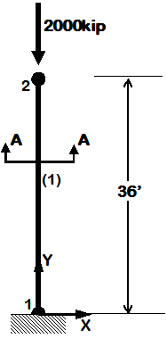
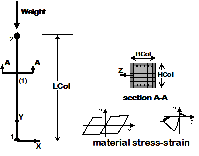
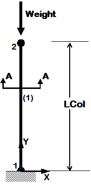
Example 1a. Elastic Cantilever Column
|
|
|
|
|
- overview of basic OpenSees input structure
- coordinates, boundary conditions, element connectivity, nodal masses, nodal loads, etc.
- two-node, one element
|
|
- static pushover analysis
- dynamic earthquake-input analysis
|
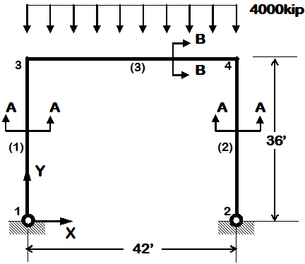
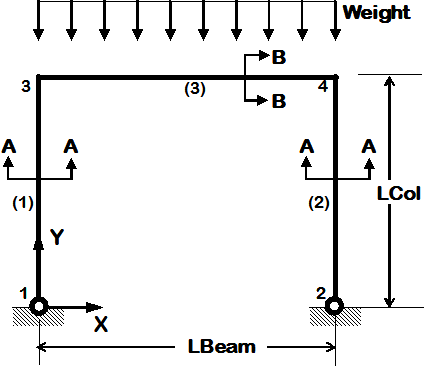
Example 1b. Elastic Portal Frame
|
|
|
|
|
- two element types
- distributed element loads
|
|
- static pushover analysis
- dynamic earthquake-input analysis
|
|
|
|
|
Objectives and Characteristics
|
Model Types
|
Analysis Types
|
|
|
|
|
|
- introduce variable: define & use
|
|
- static pushover analysis
- dynamic earthquake-input analysis
|
|
|
|
|
|
- first example of nonlinear model, set nonlinearity at section level
|
- nonlinearBeamColumn element
- uniaxial section
|
- static pushover analysis
- dynamic earthquake-input analysis
|
|
|
|
|
|
- set nonlinearity at material level
- material stress-strain response is assembled into fiber section
- reinforced-concrete fiber section
|
- nonlinearBeamColumn element
- uniaxial material
- fiber section (Reinforced-concrete fiber section)
|
- static pushover analysis
- dynamic earthquake-input analysis
|
|
|
|
|
|
Objectives and Characteristics
|
Model Types
|
Analysis Types
|
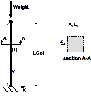
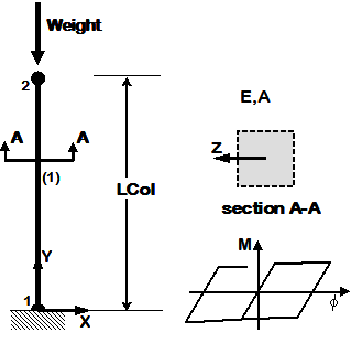
Example 3. Cantilever Column with units
|
|
|
|
|
- units, defined and used (they will be used in all subsequent examples)
- separate model-building and analysis files
- introduce PDelta effects (or not)
|
- elastic elements
- inelastic uniaxial section
- fiber section (Reinforced-concrete fiber section)
- Linear, PDelta or Corotational Transformation
|
- static pushover analysis
- dynamic earthquake-input analysis (uniform excitation)
|
Example 4. Portal Frame
|
|
|
|
|
- use previously-defined procedures to simplify input
- introduce more analysis types
- introduce procedure to read database input motion files (data with text in first lines)
|
- elastic elements
- inelastic uniaxial section
- inelastic fiber section (Reinforced-concrete fiber section)
|
- static pushover analysis
- static reversed cyclic analysis
- dynamic sine-wave input analysis (uniform excitation)
- dynamic earthquake-input analysis (uniform excitation)
- dynamic sine-wave input analysis (multiple-support excitation)
- dynamic earthquake-input analysis (multiple-support excitation)
- dynamic bidirectional earthquake-input analysis (uniform excitation)
|
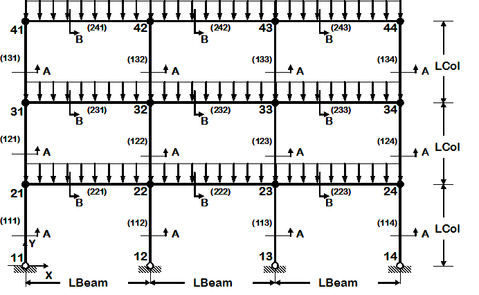
Example 5. 2D Frame, 3-story 3-bay, Reinforced-Concrete Section & Steel W-Section
|
|
|
- 2D frame of fixed geometry: 3-story, 3-bay
- nodes and elements are defined manually, one by one
|
- Reinforced-Concrete Section
- Steel W-Section
- elastic uniaxial section
- inelastic uniaxial section
- inelastic fiber section
|
- static pushover analysis
- static reversed cyclic analysis
- dynamic sine-wave input analysis (uniform excitation)
- dynamic earthquake-input analysis (uniform excitation)
- dynamic sine-wave input analysis (multiple-support excitation)
- dynamic earthquake-input analysis (multiple-support excitation)
- dynamic bidirectional earthquake-input analysis (uniform excitation)
|
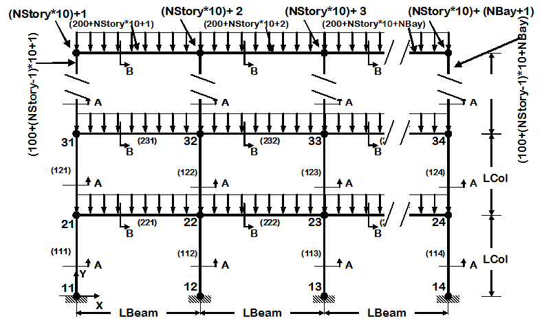
Example 6. generic 2D Frame, N-story N-bay, Reinforced-Concrete Section & Steel W-Section
|
|
|
- 2D frame geometry of variable geometry ( # stories and # bays are variables)
- node and element definition is automated
- use previously-defined procedures to view model node numbers and elements, deformed shape, and displacement history, in 2D
|
- Reinforced-Concrete Section
- Steel W-Section
- elastic uniaxial section
- inelastic uniaxial section
- inelastic fiber section
|
- static pushover analysis
- static reversed cyclic analysis
- dynamic sine-wave input analysis (uniform excitation)
- dynamic earthquake-input analysis (uniform excitation)
- dynamic sine-wave input analysis (multiple-support excitation)
- dynamic earthquake-input analysis (multiple-support excitation)
- dynamic bidirectional earthquake-input analysis (uniform excitation)
|
|
|
|
|
Objectives and Characteristics
|
Model Types
|
Analysis Types
|
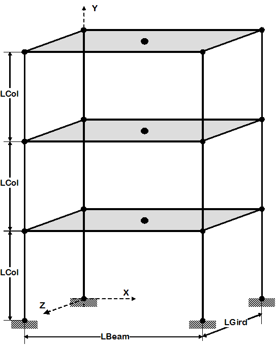
Example 7. 3D Frame, 3-story 3-bayX 3-bayZ, Reinforced-Concrete Section & Steel W-Section
|
|
- 3D frame of fixed geometry
- nodes and elements are manually manually, one by one
- introduce rigid floor diaphragm
- use previously-defined procedures to view model node numbers and elements, deformed shape, and displacement history, in 3D
|
- Reinforced-Concrete Section
- Steel W-Section
- Elastic or Fiber Section option is a variable within one input file
- rigid diaphragm
|
- static pushover analysis
- static reversed cyclic analysis
- dynamic sine-wave input analysis (uniform excitation)
- dynamic earthquake-input analysis (uniform excitation)
- dynamic sine-wave input analysis (multiple-support excitation)
- dynamic earthquake-input analysis (multiple-support excitation)
- dynamic bidirectional earthquake-input analysis (uniform excitation)
|
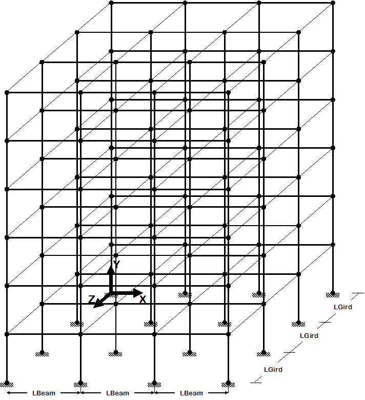
Example 8. generic 3D Frame, NStory NBayX NBayZ, Reinforced-Concrete Section & Steel W-Section
|
|
- 3D frame geometry of variable geometry ( # stories and # bays in X and Z are variables)
- node and element definition is automated
- introduce user-input interface, the user is given the option as to what to view in model
|
- Reinforced-Concrete Section
- Steel W-Section
- Elastic or Fiber Section option is a variable within one input file optional rigid diaphragm
- rigid diaphragm
|
- static pushover analysis
- static reversed cyclic analysis
- dynamic sine-wave input analysis (uniform excitation)
- dynamic earthquake-input analysis (uniform excitation)
- dynamic sine-wave input analysis (multiple-support excitation)
- dynamic earthquake-input analysis (multiple-support excitation)
- dynamic bidirectional earthquake-input analysis (uniform excitation)
|
|
|
|
|
|
|
|
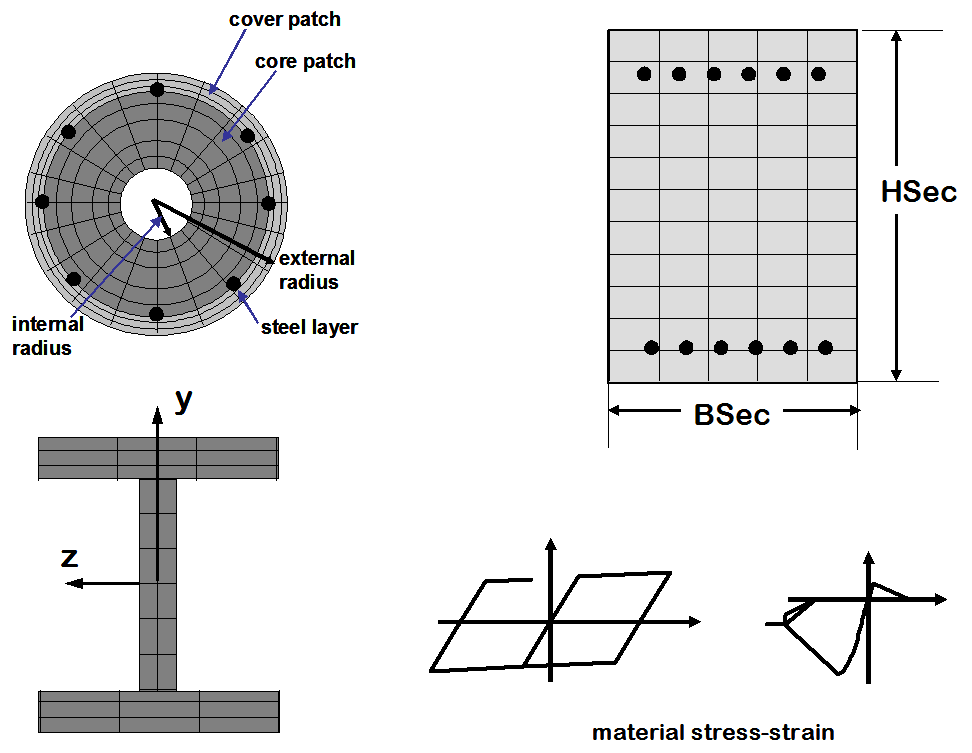
Example 9. Build & Analyze a Section
|
|
|
|
- defined section using uniaxial behavior (define moment-curvature curve) or
- define section using uniaxial materials (define stress curve) in fiber section
|
2D & 3D models of sections:
- Uniaxial Nonlinear section
- Fiber Steel W-section
- Fiber RC symmetric rectangular unconfined-concrete section
- Fiber RC symmetric rectangular unconfined & confined-concrete section
- Fiber RC generalized rectangular section
- Fiber RC generalized circular section
|
- 2D & 3D static unidirectional moment-curvature analysis
|
|
|
|
|
|
|
|
|
|
|
|
|
|
|
|
|
|
|