![]()
![]()
![]()
|
|
|
|
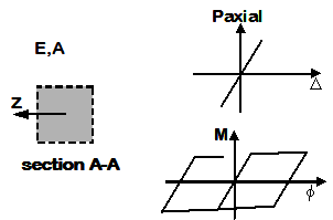
For the case of the uniaxial section, moment-curvature and axial force-deformation curves are defined independently, and numerically.
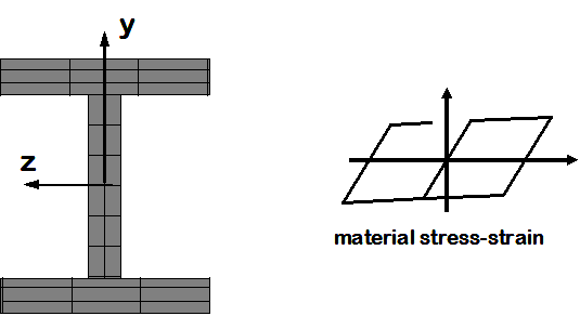
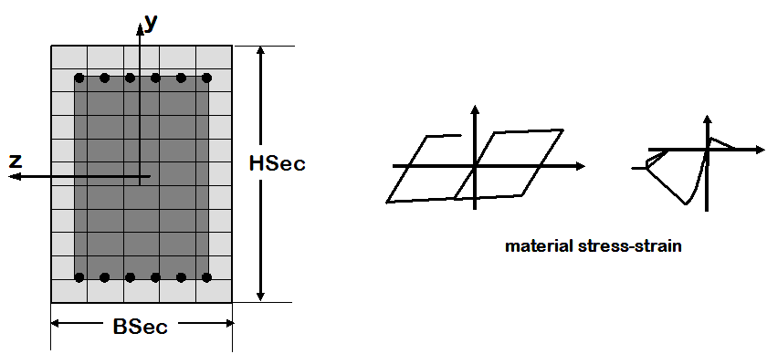
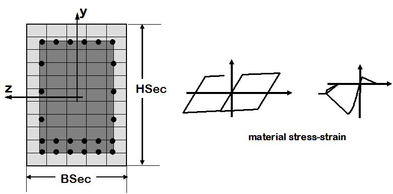
For the case of the fiber sections (steel and RC), uniaxial materials are defined numerically (stress-strain relationship) and are combined into a fiber section where moment-curvature and axial force-deformation characteristics and their interaction are calculated computationally.
While this distinction does not affect the section definition itself, it affects the degree-of-freedom associated with moment and curvature in the subsequent analysis.
There are two differences between the two models:
1. The space defined with the model command (# Define the model builder, ndm=#dimension, ndf=#dofs) |
||
|
2D: |
model BasicBuilder -ndm 2 -ndf 3; |
|
3D: |
model BasicBuilder -ndm 3 -ndf 6; |
2. In the 3D model, torsional stiffness needs to be aggregated to the section |
||
|
|
|
Uniaxial Section |
||
|
Flexure and axial behavior are uncoupled in this type of section |
|
|
|
|
Fiber Steel W SectionCoupled biaxial flexure and axial behavior |
||
|
|
|
|
|
|
Fiber Reinforced Concrete SectionCoupled biaxial flexure and axial behavior |
||
|
Rectangular Symmetric Section, Unconfined Concrete
|
|
|
Rectangular Symmetric Section, Confined Concrete Core
|
|
|
Rectangular Section generic rectangular section
|
|
|
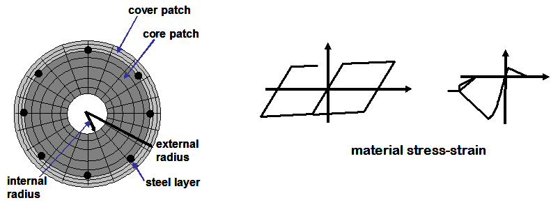
Circular Section, Confined Core
|
|
|
|
|
|
|
|
|
|
|
|
|
|