Block2D Command
Jump to navigation
Jump to search
- Command_Manual
- Tcl Commands
- Modeling_Commands
- model
- uniaxialMaterial
- ndMaterial
- frictionModel
- section
- geometricTransf
- element
- node
- sp commands
- mp commands
- timeSeries
- pattern
- mass
- block commands
- region
- rayleigh
- Analysis Commands
- Output Commands
- Misc Commands
- DataBase Commands
The block2D command generates meshes of quadrilateral elements in two or three dimensions. In three dimensions, a two-dimensional surface appropriate for shell analysis is generated.
| block2d $nx $ny $e1 $n1 element elementArgs { |
| 1 $x1 $y1 <$z1> |
| 2 $x2 $y2 <$z2> |
| 3 $x3 $y3 <$z3> |
| 4 $x4 $y4 <$z4> |
| <5> <$x5> <$y5> <$z5> |
| <6> <$x6> <$y6> <$z6> |
| <7> <$x7> <$y7> <$z7> |
| <8> <$x8> <$y8> <$z8> |
| <9> <$x9> <$y9> <$z9> |
| } |
| $nx | number of elements in the local x directions of the block |
| $ny | number of elements in the local y directions of the block |
| $e1 | element from which the mesh generation will start |
| $n1 | node from which the mesh generation will start |
| element | string defining which quadrilateral elements is being used (quad, ShellMITC4, bbarQuad, or enhancedQuad) |
| elementArgs | list of data parameters for element being used |
| {$x1, .... ,$x9}, {$y1, .... ,$y9} | coordinates of the block elements in two dimensions |
| {$z1, .... $z9} | coordinate of the block elements in third dimension (optional, default=0.0) |
NOTE:
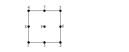
1. Only the first four nodes (1-4) are required. Nodes 5-9 are used to generate curved meshes. The user may specify any combination of nodes 5-9, omitting some of them if desired.
2. This command recognizes variable substitutions when the command arguments are placed in quotes.
EXAMPLE:
| block2D 16 4 1 1 quad "1 PlaneStrain2D 1" { |
| 1 0 0 |
| 2 40 0 |
| 3 40 10 |
| 4 0 10 |
| } |
Node numeration of a quadrilateral element: