![]()
![]()
![]()
![]()
|
|
|
|
|
Contact Authors: |
Sri Sritharan: sri[at]iastate[dot]edu Jonathan Waugh: jonwaugh[at]iastate[dot]edu |
Concrete07 is an implementation of Chang & Mander's 1994 concrete model with simplified unloading and reloading curves. Additionally the tension envelope shift with respect to the origin proposed by Chang and Mander has been removed. The model requires eight input parameters to define the monotonic envelope of confined and unconfined concrete in the following form:
uniaxialMaterial Concrete07 $matTag $fc $ec $Ec $ft $et $xp $xn $r
$matTag |
Unique material object tag |
$fc |
Floating point values defining concrete compressive strength (compression is negative) |
$ec |
Floating point values defining concrete strain at maximum compressive strength |
$Ec |
Initial Elastic modulus of the concrete |
$ft |
Floating point values defining concrete tensile strength (tension is positive) |
$et |
Floating point value defining concrete strain at maximum tensile strength |
$xp |
Non-dimensional term that defines the strain at which the straight line descent begins in tension |
$xn |
Non-dimensional term that defines the strain at which the straight line descent begins in compression |
$r |
Parameter that controls the nonlinear descending branch |
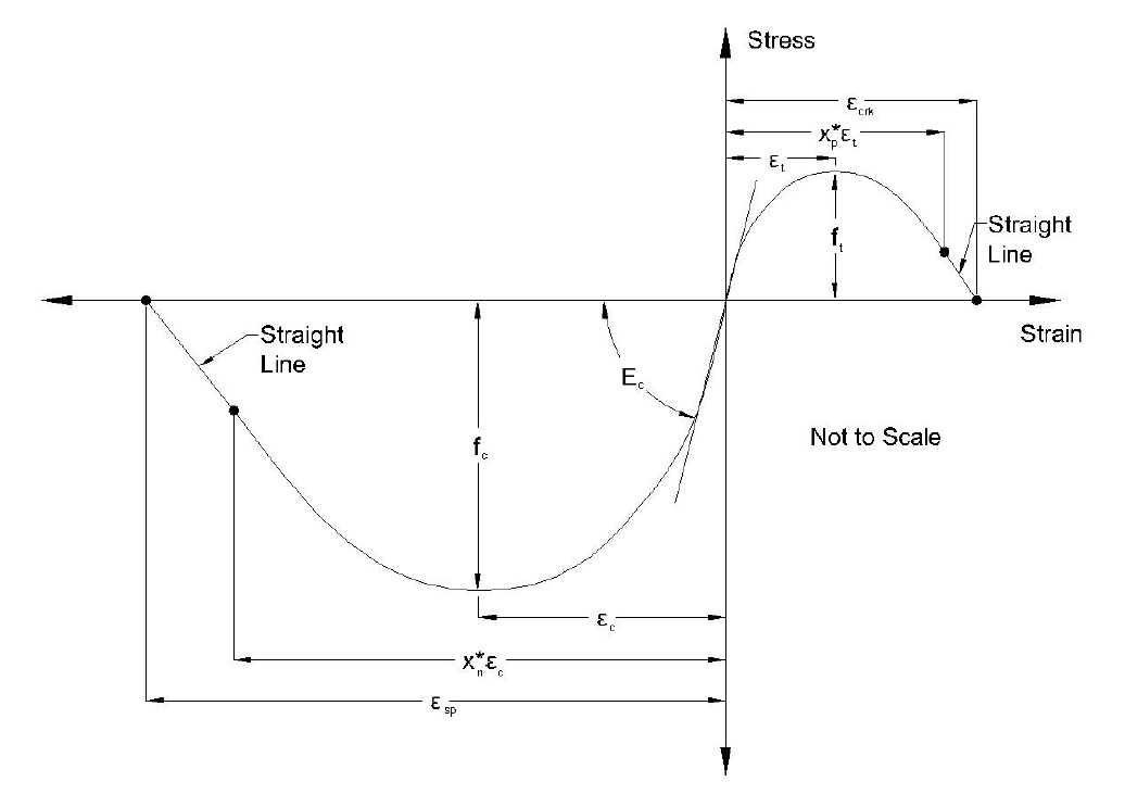
Figure 1: Concrete07 Envelope and variable definitions
For unconfined concrete, the peak compressive strength fc in the above figure is f'
c0 and corresponding
strain ec is e'c0. Assuming that the compressive strength for unconfined concrete is readily available, the
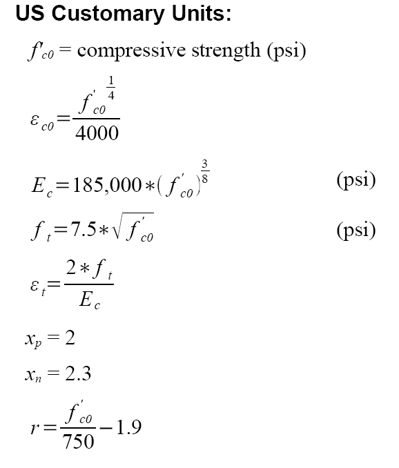
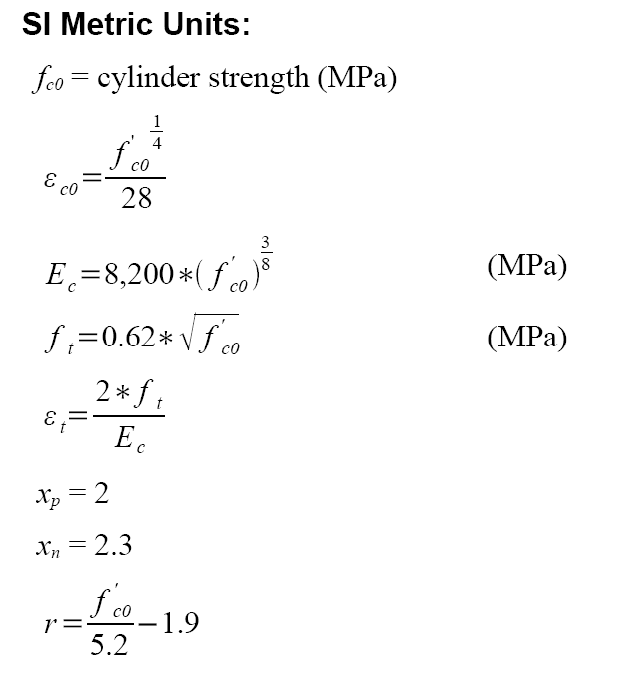
key parameters required for the model can be found using the following recommendations which
include:
Confinement increases the strength and ductility of concrete. These effects are accounted in the above
figure by replaceing the peak compressive strength and the corresponding strain with f'
cc and e'
cc,
respectively. The value of r is also decreased.
The recommended approach to define all critical parameters needed to model the confined concrete
under compression are as follows:
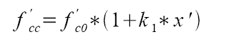
where:
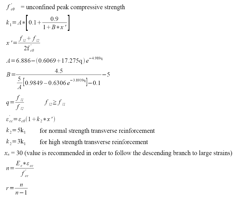
The monotonic envelope for the tension side of the confined concrete follows the same curve that is
used for unconfined concrete..
The hysteretic rules for cyclic behavior of confined and unconfined concrete is built into the model and
requires no further input from the user. These rules generally follow the recommendations of Chang
and Mander, which was established based on statistical regression analysis on the experimental data
from cyclic compression tests of a number of researchers. However, three simplifications were made to
the rules proposed by Chang and Mander which are:
1) Instead of the power function for unloading and reloading paths, Concrete07 uses tri-linear paths for
unloading and reloading. The reason for this change is is to increase the computational efficiency of
the model, as well as numerical stability.
2) The original model shifts the tension envelope as compression reloading after a reversal occurs.
This shift is deemed unnecessary and not implemented in Concrete07.
3) The original model requires an additional strain be applied beyond the unloading strain to rejoin the
monotonic envelope. The Concrete07 rejoins the envelope at the unloading strain; this simplification
increases the numerical stability and computational efficiency.
A full description of the Concrete07 material model, modifications to the Chang and Mander concrete
model, and the effects of Concrete07 in improving the simulation capacity of OpenSees is given in
Waugh (2007).
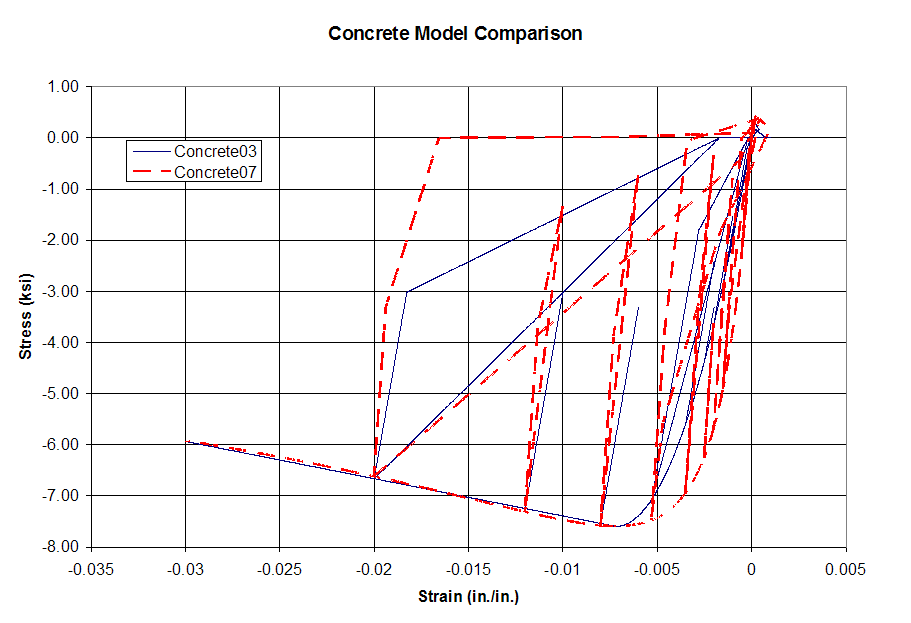
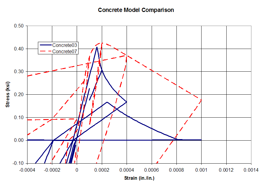
A comparison of the cyclic behavior of Concrete07 and Concrete03 is shown in below; a magnified
view of the tension region is shown separately. A confined concrete is used in this illustration so that
the differences between the models behavior is more pronounced.
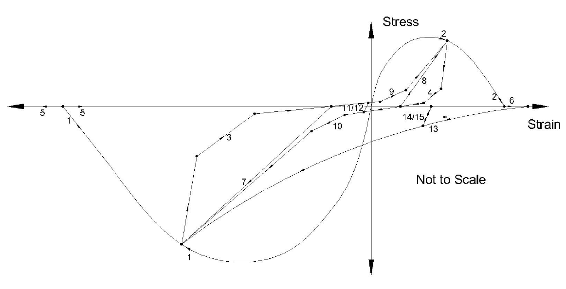
Figure 2: Hysteretic behavior of Concrete07
Concrete07 gives larger residual displacements than Concrete03. Concrete07 also has a higher initial
stiffness compared with Concrete03 and has a much slower softening post-peak in tension. Chang and
Mander state that the abrupt loss of capacity shown in Concrete03 in tension is due to testing
conditions and not representative of the true material behavior.
If the material model is used in a section that is going to be subjected to cyclic loading, problems can
occur if there is no axial load on the section. The section should be subjected to axial load due to the
self weight of the element. If the material is loaded into tension without any compression strain, and
then reversed, the model will target -0.00002 strain if cracking has not occurred or 5% of the peak
strain if cracking has occurred. The increased value after cracking is due to material being wedged in
the open cracks.
Users are encouraged to apply some axial load to the section equal to the self weight of the element or a
small amount if the user does want minimal axial load. Less than 0.05% of f'cAg is adequate to ensure a
stable response. This will then be used instead of the default behavior described above.
Chang, G.A., and Mander, J.B., (1994) "Seismic Energy Based Fatigue Damage Ananlysis of Bridge
Columns: Part 1 – Evaluation of Seismic Capacity," NCEER Technical Report No. NCEER-94-0006,
State University of New York, Buffalo, N.Y.,
Waugh, PhD Thesis (In progress) 2007.