![]()
![]()
![]()
|
|
|
|
This command is used to construct a linear coordinate transformation (LinearCrdTransf) object, which performs a linear geometric transformation of beam stiffness and resisting force from the basic system to the global-coordinate system.
For a two-dimensional problem:
geomTransf Linear $transfTag <-jntOffset $dXi $dYi $dXj $dYj>
For a three-dimensional problem:
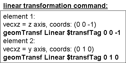
geomTransf Linear $transfTag $vecxzX $vecxzY $vecxzZ <-jntOffset $dXi $dYi $dZi $dXj $dYj $dZj>
$transfTag |
unique identifier for CrdTransf object |
$vecxzX $vecxzY $vecxzZ |
X, Y, and Z components of vecxz, the vector used to define the local x-z plane of the local-coordinate system. The local y-axis is defined by taking the cross product of the vecxz vector and the x-axis. These components are specified in the global-coordinate system X,Y,Z and define a vector that is in a plane parallel to the x-z plane of the local-coordinate system. These items need to be specified for the three-dimensional problem. |
$dXi $dYi $dZi |
joint offset values -- absolute offsets specified with respect to the global coordinate system for element-end node i (the number of arguments depends on the dimensions of the current model) (optional) |
$dXj $dYj $dZj |
joint offset values -- absolute offsets specified with respect to the global coordinate system for element-end node j (the number of arguments depends on the dimensions of the current model) (optional) |
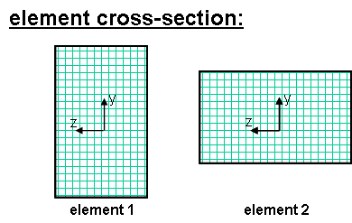
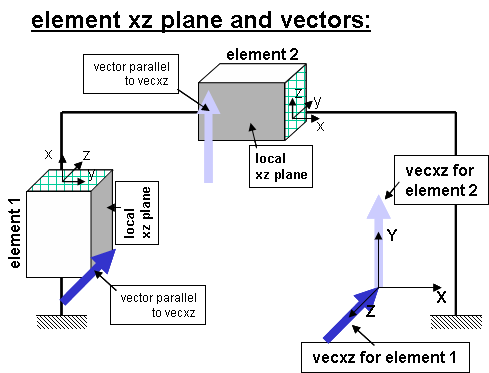
The element coordinate system is specified as follows:
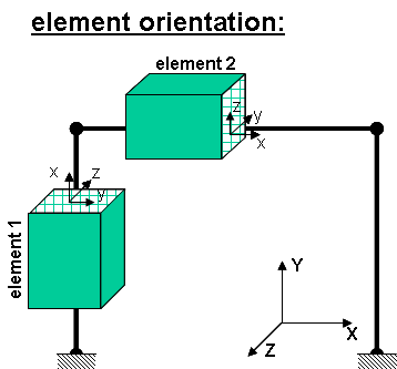
The x-axis is the axis connecting the two element nodes; the y- and z-axes are then defined using a vector that lies on a plane parallel to the local x-z plane -- vecxz. The local y-axis is defined by taking the cross product of the vecxz vector and the x-axis.. The section is attached to the element such that the y-z coordinate system used to specify the section corresponds to the y-z axes of the element.
The following figures should aid in understanding the vector vecxz definition:
|
|
|