![]()
![]()
![]()
|
|
|
|
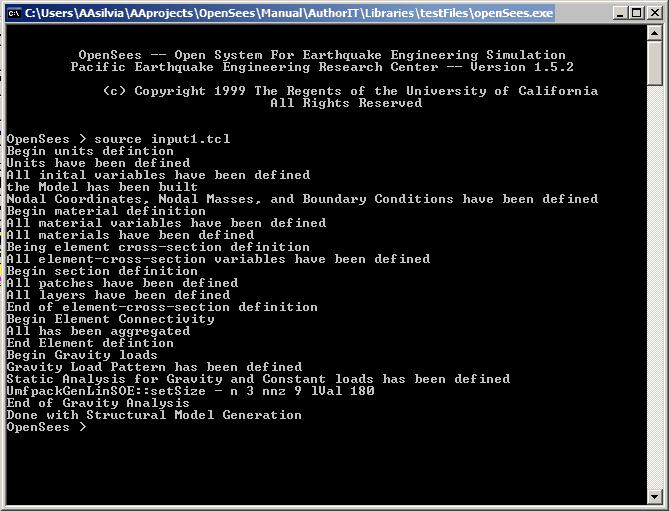
To enable error-checking, it is good practice to place markers within the input file. Markers are simple statements to be output to the screen using the puts tcl command. These markers tell the user what commands have been completed. This way, if an error occurs, the user is able to find the location of the error. Here is an example, where puts commands are placed here and there in the input1.tcl file:
puts "Begin units defintion"
# DEFINE UNITS
set in 1.; # define basic unit -- length
set sec 1.; # define basic unit -- time
set kip 1.; # define basic unit -- weight (or define force, but not both)
set ksi [expr $kip/pow($in,2)]; # define engineering units
set psi [expr $ksi/1000.];
set ft [expr 12.*$in];
set g [expr 32.2*$ft/pow($sec,2)]; # gravitational acceleration
set PI [expr 2*asin(1.0)]; # define constants
set U 1.e10; # a really large number
set u [expr 1/$U]; # a really small number
puts "Units have been defined"
# define GEOMETRY variables
set Hcol [expr 6.*$ft]; # column diameter
set Lcol [expr 36*$ft]; # column length
set GrhoCol 0.015; # column longitudinal-steel ratio
set Weight [expr 3000.*$kip]; # superstructure weight
set Rcol [expr $Hcol/2]; # COLUMN radius
set Acol [expr $PI*pow($Rcol,2)]; # column cross-sectional area
set cover [expr $Hcol/15]; # column cover width
set G $U; # Torsional stiffness Modulus
set J 1.; # Torsional stiffness of section
set GJ [expr $G*$J]; # Torsional stiffness
# define COLUMN REINFORCEMENT variables
set NbCol 20; # number of column longitudinal-reinforcement bars
set AsCol [expr $GrhoCol*$Acol]; # total steel area in column section
set AbCol [expr $AsCol/$NbCol]; # bar area of column longitudinal reinforcement
# define GRAVITY variables
set Mass [expr $Weight/$g]; # mass of superstructure
set Mnode [expr $Mass]; # nodal mass for each column joint
# define DAMPING variables from $xDamp --SDOF system, use stiffness proportional damping only
set xDamp 0.02; # modal damping ratio
# ------ set analysis variables
set DxPush [expr 0.1*$in]; # Displacement increment for pushover analysis
set DmaxPush [expr 0.05*$Lcol]; # maximum displamcement for pushover analysis
set gamma 0.5; # gamma value for newmark integration
set beta 0.25; # beta value for newmark integration
set DtAnalysis [expr 0.005*$sec]; # time-step Dt for lateral analysis
set DtGround [expr 0.02*$sec]; # time-step Dt for input grond motion
set TmaxGround [expr 50.*$sec]; # maximum duration of ground-motion analysis
puts "All inital variables have been defined"
# define ModelBuilder
model basic -ndm 2 -ndf 3; # basic: modelbuilder type, ndm= number of dimensions, ndf= #dof/node
puts "the Model has been built"
# Nodal Coordinates and Nodal Masses
node 1 0. 0.; # column base is located at the origin of the plane
node 2 0. $Lcol -mass $Mnode 0. 0.; # the column end has one translational mass in the x direction, only
# Boundary Conditions
fix 1 1 1 1; # fixed base
fix 2 0 0 0; # free end
puts "Nodal Coordinates, Nodal Masses, and Boundary Conditions have been defined"
puts "Begin material definition"
# Confined concrete:
set fc [expr -5.5*$ksi]; # CONCRETE Compressive Strength, ksi (+Tension, -Compression)
set Ec [expr 57*$ksi*sqrt(-$fc/$psi)]; # Concrete Elastic Modulus
set fc1C [expr 1.26394*$fc]; # CONFINED concrete (mander model), maximum stress
set eps1C [expr 2.*$fc1C/$Ec]; # strain at maximum stress
set fc2C $fc; # ultimate stress
set eps2C [expr 5*$eps1C]; # strain at ultimate stress
# Unconfined concrete:
set fc1U $fc; # UNCONFINED concrete (todeschini parabolic model), maximum stress
set eps1U -0.003; # strain at maximum stress
set fc2U [expr 0.1*$fc]; # ultimate stress
set eps2U -0.006; # strain at ultimate stress
# Concrete02 variables:
set lambda 0.1 ; # ratio between unloading slope at $epscu and initial slope
set ftC [expr -$fc1C/10.]; # tensile strength +tension
set ftU [expr -$fc1U/10.]; # tensile strength +tension
set Ets [expr $Ec/10.]; # tension softening stiffness
# reinforcing steel
set Fy [expr 68.*$ksi]; # STEEL yield stress
set Es [expr 29000.*$ksi]; # modulus of steel
set epsY [expr $Fy/$Es]; # steel yield strain
set Fu [expr 95.2*$ksi]; # ultimate stress of steel
set epsU 0.1; # ultimate strain of steel
set E2 [expr ($Fu-$Fy)/($epsU-$epsY)]; # post-yield tangent stiffness
set Bs [expr $E2/$Es]; # post-yield stiffness ratio of steel
# set up parameters for column section and element definition
set IDcore 1; # ID tag for core concrete
set IDcover 2; # ID tag for cover concrete
set IDsteel 3; # ID tag for steel
puts "All material variables have been defined"
uniaxialMaterial Concrete02 $IDcore $fc1C $eps1C $fc2C $eps2C $lambda $ftC $Ets; # CORE CONCRETE
uniaxialMaterial Concrete02 $IDcover $fc1U $eps1U $fc2U $eps2U $lambda $ftU $Ets; # COVER CONCRETE
uniaxialMaterial Steel01 $IDsteel $Fy $Es $Bs; # REINFORCING STEEL
puts "All materials have been defined"
puts "Being element cross-section definition"
# element cross-section
# Notes
# The center of the reinforcing bars are placed at the inner radius
# The core concrete ends at the inner radius (same as reinforcing bars)
# The reinforcing bars are all the same size
# The center of the section is at (0,0) in the local axis system
# Zero degrees is along section y-axis
set IDcolFlex 2; # ID tag for column section in flexure, before aggregating torsion
set riCol 0.0; # inner radius of column section
set roCol $Rcol; # outer radius of column section
set nfCoreR 8; # number of radial fibers in core (number of "rings")
set nfCoreT 16; # number of tangential fibers in core (number of "wedges")
set nfCoverR 2; # number of radial fibers in cover
set nfCoverT 16; # number of tangential fibers in cover
# cover - cover thickness, has been defined with the geometry
# IDcore - material tag for the core patch, has been defined with the materials
# IDcover - material tag for the cover patches, has been defined with the materials
# IDsteel - material tag for the reinforcing steel, has been defined with the materials
# NbCol # number of column longitudinal-reinforcement bars, has been defined with the geometry
# AbCol # bar area of column longitudinal reinforcement, has been defined with the geometry
puts "All element-cross-section variables have been defined"
puts "Begin section definition"
section fiberSec $IDcolFlex {
set rc [expr $roCol-$cover]; # Core radius
patch circ $IDcore $nfCoreT $nfCoreR 0 0 $riCol $rc 0 360; # Define the core patch
patch circ $IDcover $nfCoverT $nfCoverR 0 0 $rc $roCol 0 360; # Define the cover patch
puts "All patches have been defined"
set theta [expr 360.0/$NbCol]; # Determine angle increment between bars
layer circ $IDsteel $NbCol $AbCol 0 0 $rc $theta 360; # Define the reinforcing layer
puts "All layers have been defined"
}
puts "End of element-cross-section definition"
puts "Begin Element Connectivity"
# element connectivity
set IDcolTors 10; # ID tag for column section in torsion
set IDcolSec 1; # ID tag for column section
uniaxialMaterial Elastic $IDcolTors $GJ; # Define torsional stiffness
section Aggregator $IDcolSec $IDcolTors T -section $IDcolFlex; # attach torsion to flexure and create a new section IDtag
puts "All has been aggregated"
set IDcolTrans 1; # ID tag for column transformation, defining element normal
geomTransf Linear $IDcolTrans; # Linear: no second-order effects
set np 5; # Number of integration points
element nonlinearBeamColumn 1 1 2 $np $IDcolSec $IDcolTrans
puts "End Element defintion"
puts "Begin Gravity loads"
# apply constant gravity load (and other constant loads)
set Pdl [expr $Weight]; # gravity axial load per column
pattern Plain 1 Linear {
load 2 0.0 -$Pdl 0.0
}
puts "Gravity Load Pattern has been defined"
# set up solution procedure
system UmfPack; # solution procedure, Super-LU, how it solves system of equations
constraints Plain; # how it handles boundary conditions, enforce constraints through the transformation
# set up convergence criteria
test NormDispIncr 1.0e-5 10 0; # tolerance, max no. of iterations, and print code , 1: every iteration
algorithm Newton; # use Newton's solution algorithm: updates tangent stiffness at every iteration
numberer RCM; # renumber dof's to minimize band-width (optimization)
# set up load steppring
integrator LoadControl 0.1 1 0.1 0.1; # variable load-stepping
# set up type of analysis, static for gravity
analysis Static
puts "Static Analysis for Gravity and Constant loads has been defined"
initialize
# RUN GRAVITY ANALYSIS
analyze 10
loadConst -time 0.0
puts "End of Gravity Analysis"
# print to screen that you are done with this step:
puts "Done with Structural Model Generation"
The OpenSees control window will look like this:
When there is an error, it can be localized:
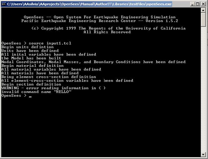
Based on the markers, the erroneous command is located within the section definition, between the two puts commands.
puts "Begin section definition"
section fiberSec $IDcolFlex {
set rc [expr $roCol-$cover]; # Core radius
patch circ $IDcore $nfCoreT $nfCoreR 0 0 $riCol $rc 0 360; # Define the core patch
HELLO
patch circ $IDcover $nfCoverT $nfCoverR 0 0 $rc $roCol 0 360; # Define the cover patch
puts "All patches have been defined"
set theta [expr 360.0/$NbCol]; # Determine angle increment between bars
layer circ $IDsteel $NbCol $AbCol 0 0 $rc $theta 360; # Define the reinforcing layer
puts "All layers have been defined"
}
|
|
|