![]()
![]()
|
|
|
The example files (PR1.tcl, procMKPC.tcl, procUniaxialPinching.tcl, procRC.tcl) create a model of a RC beam column sub-assemblage (Figure 1). The cruciform is subjected to constant gravity load at nodes 4 and 7 and pseudo-static cyclic lateral load under displacement control at node 10. The beam-column-joint region (element number 7) is represented using a beamColumnJoint element (Figure 2), and the beams and columns (element numbers 1 through 6) are modeled using the nonlinearBeamColumn element. The beam-column joint consists of 13 components that may have different material constitutive models; in this example 9 of the 13 components utilize the nonlinear material model – Pinching4. Figure 3 shows the displacement history for node 10.
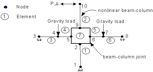
Figure 1: Cruciform model
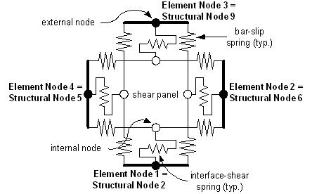
Figure 2: Beam Column Joint Element
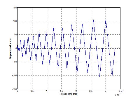
Figure 3: Displacement history for Node 10
Tcl Scripts:
The following tcl script files are used to run the examples:
The p-delta response of cruciform, along with the response of each of the nonlinear joint components is shown below. The shear panel response shows the moment-curvature relationships whereas the bar slips at the beam top and bottom are represented by the force-slip plots (Figure 4).

Figure 4: Nonlinear Joint component response
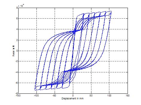
Figure 5. P-delta response of the cruciform