BuildingTclViewer Input Menu: Difference between revisions
| Line 217: | Line 217: | ||
:The program recalculates the values and redraws the picture to scale once the cursor leaves the text box. Therefore, do not exit the text box until the correct value is input. An error may result if this step is not done properly. | :The program recalculates the values and redraws the picture to scale once the cursor leaves the text box. Therefore, do not exit the text box until the correct value is input. An error may result if this step is not done properly. | ||
[[Image:BuildingTclViewerInputElevationEditBayWidth.JPG|link=BuildingTclViewer Input Menu]] | [[Image:BuildingTclViewerInputElevationEditBayWidth.JPG|650px|link=BuildingTclViewer Input Menu]] | ||
3. Increase the number of stories and bays iteratively with their heights and widths | 3. Increase the number of stories and bays iteratively with their heights and widths | ||
[[Image:BuildingTclViewerInputElevationEditStoryHeight.JPG|link=BuildingTclViewer Input Menu]] | [[Image:BuildingTclViewerInputElevationEditStoryHeight.JPG|650px|link=BuildingTclViewer Input Menu]] | ||
[[Image:BuildingTclViewerInputElevationNoStoryBay.JPG|link=BuildingTclViewer Input Menu]] | [[Image:BuildingTclViewerInputElevationNoStoryBay.JPG|link=BuildingTclViewer Input Menu]] | ||
Revision as of 04:49, 29 December 2009

Input Management -- create or edit
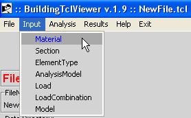
The user can either create new or edit a library of the following BuildingTcl objects:
- Material
- Section
- ElementType
- AnalysisModel
- Load
- LoadCombination
- Model
These BuildingTcl objects have been presented in the BuildingTcl Command Language Manual
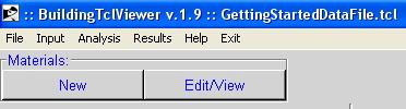
Common Characteristics
All of these input option begin with the selection of creating a new object, or edit an existing one. The case for material is shown here.
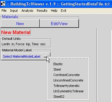
New
When a new object is to be created, the user must first select the BuildingTcl model used for such object.
The input arguments are dependent on the model selected. However, they are grouped in the following:
- Unique Object label
- The user specifies this label
- The default value is the model label. If this label has already been used, the program adds an underscore and an identifying number after this label.
- Save
- Save the newly-defined object into the library.
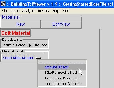
Edit
The user must first select a previously-defined BuildingTcl object.
The input arguments are dependent on the model used for the object. The user can change the model, however, all input will be lost and default values are restored.
- Modify/Save
- The new values for the object replace the previously-defined ones, which cannot be restored.
- Save As...
- A new object with a new label will be saved into the library without affecting the original object.
- The user can specify a new name for this object. The default will be the name of the original object, with an underscore and a count number after it.
New & Edit
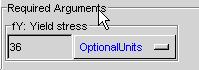
- Required Arguments
- These arguments must be specified by the user.
- Optional Arguments
- These arguments can be specified by the user. The initial value of these arguments is the default value
NOTE: The Required and Optional Arguments text boxes are expanded and contracted when their title (Required Arguments or Optional Arguments) are cliked on by the mouse.
Units
The input for most arguments has optional units. If no units are specified, the program assumes that the input is consistent with the basic units specified at the beginning. The user may, however, select the units from a list of possible units. The possible units are specific to each argument. Here are three examples:
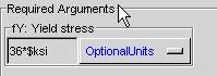
- No units specified:
- Units specified manually, or from script:
- Units selected from pull-down menu:
 resulting in:
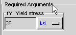
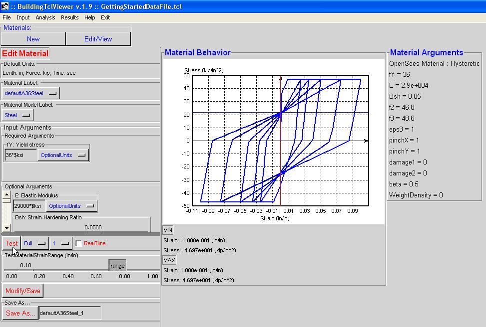
Material
The following items are found in the Input Menu for a Material:
- Material Label
- Material Model Label
- Input Arguments
- Required Arguments
- Optional Arguments
- Material Test:
- Test Button -- perform test. A graphic of the stress-strain response is shown after the OpenSees analysis on the material has been done. The material arguments are posted next to this graph.
- Test-Load Type -- different types of monotonic or cyclic loading patterns can be selected
- Number of Test Cycles -- the user can select the number of cycles performed at each peak in the load pattern
- RealTime Option -- when the user checks this option, the analysis data is diplayed real-time. This feature enables a better appreciation of the loading pattern, but slows down the analysis significantly. The real-time display window is closed automatically by the program once the analysis has terminated, so it may be visible for a very short time. The user can stop the analysis at any time using the Stop button in the real-time display window.
- Material Strain Range -- Maximum strain for test load
- range of MaterialStrainRange -- change the scale of the range for the MaterialStrainRange
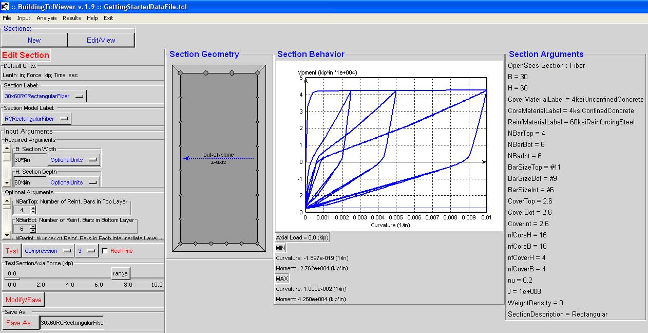
Section
The following items are found in the Input Menu for a Section:
- Section Label
- Section Model Label
- Input Arguments
- Required Arguments
- Optional Arguments
- Section Test:
- Test Button -- perform test. A graphic of the moment-curvature response is shown after the OpenSees analysis on the Section has been done. The Section arguments are posted next to this graph.
- Test-Load Type -- different types of monotonic or cyclic loading patterns can be selected
- Number of Test Cycles -- the user can select the number of cycles performed at each peak in the load pattern
- RealTime Option -- when the user checks this option, the analysis data is diplayed real-time. This feature enables a better appreciation of the loading pattern, but slows down the analysis significantly. The real-time display window is closed automatically by the program once the analysis has terminated, so it may be visible for a very short time. The user can stop the analysis at any time using the Stop button in the real-time display window.
- Section Axial Force -- Axial Load on section at which the moment-curvature analysis is performed.
- range of SectionStrainRange -- change the scale of the range for the Axial Load
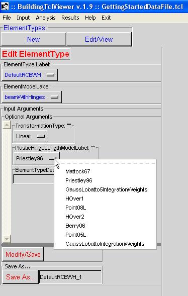
ElementType
BuildingTcl comes with a set of pre-loaded Default element types for Columns, Beams and Braces. This library of element types should be sufficient in defining a model. It is recommended that the user modify these pre-loaded element types and save them under a new name.
In the current release, there are no graphical displays of the element types available.
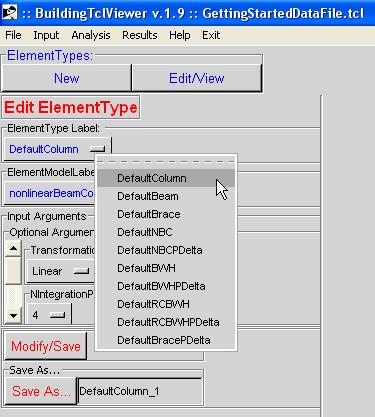
For more information, the user should consult the BuildingTcl Manual: BuildingTcl -- addElementType.
Here is an example of the input:
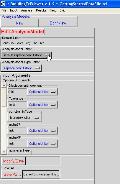
AnalysisModel
BuildingTcl comes with a set of pre-loaded Default AnalysisModels. This library of element types should be sufficient in defining a model. It is recommended that the user modify these pre-loaded AnalysisModela and save them under a new name.
In the current release, there are no graphical displays of the AnalysisModels available.
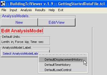
For more information, the user should consult the BuildingTcl Manual: BuildingTcl -- addAnalysisModel.
Here is an example of the input:
Load
BuildingTcl comes with a set of pre-loaded Default Loads. It is recommended that the user modify these pre-loaded AnalysisModela and save them under a new name. The library of loads is not complete with the default Loads alone, though, since no default can be created for a file-input ground motion.
In the current release, there are no graphical displays of the Loads available.
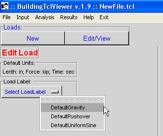
For more information, the user should consult the BuildingTcl Manual: BuildingTcl -- addLoad.
Here is an example of the input:
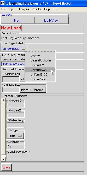
Special Case: GMfilename Selection
For the cases of Uniform ground motion, the user is required to specify the filename(s) and the folder location of the filename(s). In BuildingTclViewer, the user selects the location of the input file manually, via windows widget. Once the file is selected, the program automatically uses the folder of the selected file as the GMdirectory. For multi-directional input, ALL ground motion files MUST be located in the same directory.
LoadCombination
A LoadCombination is the final step in defining the loading and analysis. It uses previously-defined Loads and previously-defined AnalysisModels. In the current release, there is only one LoadCombinationModel: DefaultLoadCombinationModel. The user is required to select it to maintain consistency with the rest of the input.
In the solution procedure, the program performs the following steps 0. Define the Model Nodes and Elements -- (described elsewhere)
- Gravity Loads
1. For each Gravity Load, one at a time:
- 1a. Calculate nodal masses based on the LoadFactor and the InertialMassFactor defined in the LoadCombination
- 1b. Calculate nodal vertical forces based on the LoadFactor defined in the LoadCombination
2. Add up all masses and gravity loads for each node. 3. Define OpenSees nodal Masses and Loads in one load case 2. Perform Eigen analysis to determine the first three periods of the model. The current release prints this output to the OpenSeesTk window. 3. Perform Load-Controlled analysis using the AnalysisModelLabel specified in the LoadCombination.
- Lateral Loads
4. Define Load and Analysis parameters and perform the analysis for each Lateral-Load case in sequence.
- NOTE
- Control of a number of Load and AnlysisModel Arguments has been made available at the LoadCombination level. The values specified at this level supercede the previously-defined ones.
- NOTE
- In the current release, different types of Lateral Loads cannot be combined in the same LoadCombination:
- All StaticPushovers must be in the same direction
- A StaticPushover cannot be followed by a dynamic ground motion.
- NOTE
- The GravityLoad and LateralLoad boxes can be expanded/contracted by clicking the mouse on "Gravity Loads:" and "Lateral Loads:"
The initial input screen for LoadCombinations looks as shown below:

While the Required Arguments and Default Arguments input is the same as the other input, the LoadCombination Input has the additional input for Gravity Loads and Lateral Loads. To define a load, press the "add Gravity Load" and "add Lateral Load" buttons for each time a load is to be added.
An example of the input is shown below:

Model
There are three ModelTypes available in BuildingTcl:
- Elevation Model
- Define elevation geometry (bay widths and story heights)
- Define frame elements (Columns, Beams, etc)
- Define gravity Loads
- Define support boundary conditions
- Plan Model
- Define floor plan bay widths in two directions
- Label plan lines
- 3DFrame Model
- Select one Plan model which controls the bay widths
- Assign different elevations on the plan model
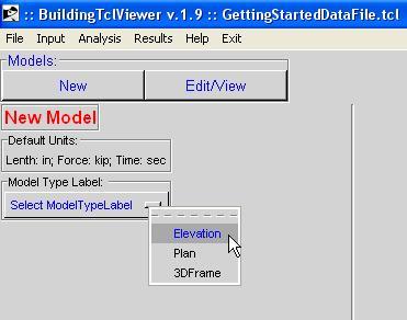
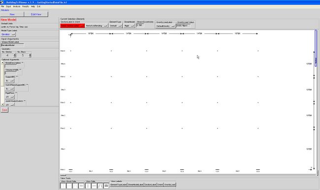
Elevation Model
The Elevation input window starts as shown below:
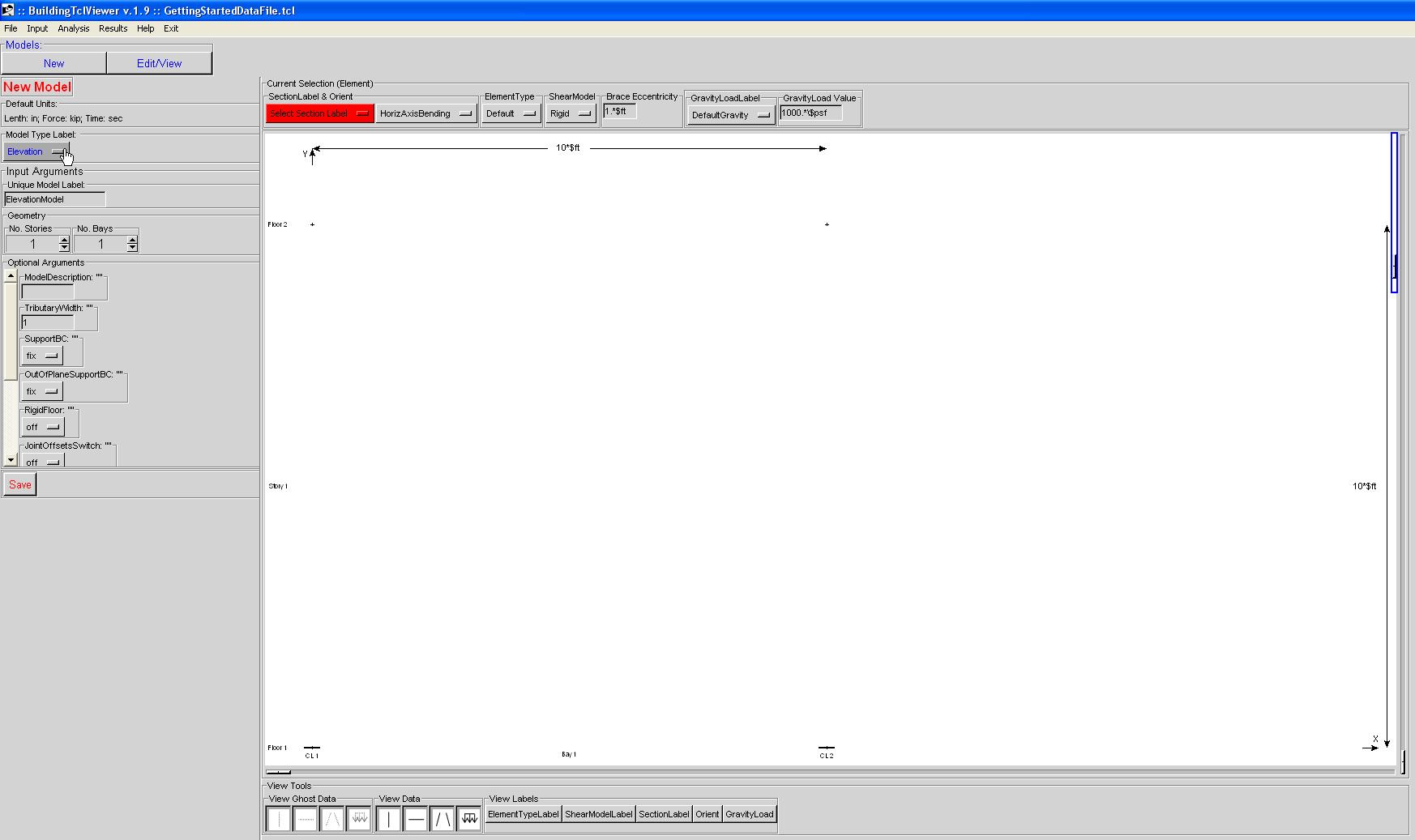
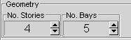
Geometry
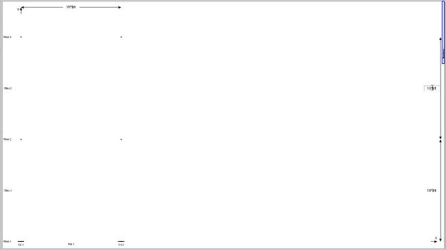
The bay width and story height are modified directly on the dimension text. The number of stories and bays is controlled by the controls in the left menu. The bay width and story height of any additional stories and bays is set equal to the previous one. The user should follow these steps 1. The first bay will be the bay on the bottom left of the elevation. 2. Manually modify the bay width and story height to the desired values.
- The program recalculates the values and redraws the picture to scale once the cursor leaves the text box. Therefore, do not exit the text box until the correct value is input. An error may result if this step is not done properly.
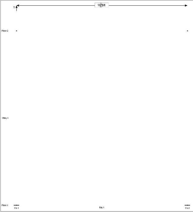
3. Increase the number of stories and bays iteratively with their heights and widths