GiD ProblemTypes for 2D Slope Analysis Input File Generation
Example prepared by: Christopher McGann and Pedro Arduino, University of Washington
Return to OpenSees Examples Page
This article describes the use of the tool GiD as a pre- and post-processor for a 2D analysis of a soil continua in OpenSees. Two separate procedures are made available for download, one which creates an input file for an effective stress analysis using nine node quadrilateral elements, and one which creates an input file for a total stress analysis using four node quadrilateral elements. Only the former procedure will be described in this article, as the procedure for the four node elements is very similar, but less complex. The nine node element procedure discussed in this article was used to develop the input file for the Dynamic Effective Stress Analysis of a Slope example posted in the practical examples section of this manual.
GiD can be used for many purposes, one of which is as a pre- or post-processor for a finite element package. For pre-processing, the interaction between GiD and a particular outside program is fully customizable via a series of files called a problem type. The files which make up the problem type define things such as which materials can be used, which conditions such as nodal degrees of freedom or fixities can be assigned, and the formatting and syntax of the input file which is generated from the GiD mesh. Further information on pre-processing using GiD, or the use of GiD in general, can be found in the GiD manual.
The files which define the nine node element procedure discussed in this article include:
- The GiD problem type, UWnineQuad2Dup.gid, which consists of the following individual files:
- UWnineQuad2Dup.bas, a template file which defines how the OpenSees input file is generated from the GiD input
- UWnineQuad2Dup.mat, a file which defines materials for use in GiD
- UWnineQuad2Dup.cnd, a file which defines certain conditions necessary for the analysis for use in GiD
- UWnineQuad2Dup.bat, a batch file which renames the file output by the procedure as directory_name.tcl
- UWnineQuad2Dup.tcl, a file containing two tcl procedures necessary to the creation of the input file
The files which define the four node element procedure include:
- The GiD problem type, UWquad2D.gid, which consists of the following individual files (descriptions correspond to those listed above):
- UWquad2D.bas
- UWquad2D.mat
- UWquad2D.cnd
- UWquad2D.bat
All of the files mentioned above can be downloaded by clicking here.
The UWnineQuad2Dup.gid Problem Type
The UWnineQuad2Dup.gid problem type can be used in conjunction with GiD to generate an OpenSees input file a dynamic analysis of a 2D soil continua underlain by an elastic half-space. The problem type is set up for nine node quadrilateral elements with an additional pore pressure degree of freedom at the corner node, and uses a Lysmer-Kuhlemeyer (1969) to account for the finite rigidity of the underlying elastic half-space. Each file in the problem type performs a specific task, and together they allow GiD to be used as an effective pre-processor for this type of problem in OpenSees.
It is important to note that using this problem type to create an input file for a particular analysis does not guarantee that the generated input file will function perfectly. It is a useful tool which greatly simplifies the creation of a mesh and the assignment of materials and conditions for 2D problems, but it does not automatically create perfect input files. The user must make sure that the input file was properly generated and must exercise engineering judgment in the creation of the analysis.
Conditions File - UWnineQuad2Dup.cnd
This file defines the conditions which can be applied to the mesh or geometry in GiD. These conditions are then used by the template file, UWnineQuad2Dup.bas, to generate the OpenSees input file from the GiD mesh. The format of the condition file is described in the GiD manual.
Essentially, this file is a list of the conditions that apply to this particular problem. These conditions are used to define the degrees of freedom and the point constraints (fixities) for the nodes, to define the sets of nodes which are tied in equalDOF to create the free-field columns discussed in the slope analysis example, to identify the slave node for the Lysmer-Kuhlemeyer dashpot element, and to specify the locations of nodal masses used to represent the dynamic effects of a body of water. The value assigned to each question in each condition is the default value for this condition. These values can be changed when assigning the conditions in GiD.
Material File - UWnineQuad2Dup.mat
This file specifies the nDMaterials which can be assigned to the elements in the GiD-generated mesh. As with the condition file, the material file is a list of materials using the format discussed in the GiD manual. The materials which are included in the material file correspond with the intentions of this problem type to be used for geotechnical analyses. The available materials for this problem type are:
- ElasticIsotropic
- PressureDependMultiYield
- PressureDependMultiYield02
- PressureIndependMultiYield
- J2Plasticity
Each of these materials are supplied with default values which can be changed when assigning them in GiD. There are two tabs for each material type, one for the material parameters (e.g. shear modulus, mass density), and one for the parameters which are assigned in the nine node quadrilateral element (undrained bulk modulus, fluid mass density, horizontal and vertical permeabilities, and body forces). The problem type is set up so each material has a corresponding set of element parameters to allow for the analysis of layered soil profiles.
New materials can be made in GiD using these base materials as templates. For example, in a soil profile in which there are several layers of sand, different versions of the PressureDependMultiYield wich have separate names and sets of parameters can be created and assigned to the individual sand layers.
Template File - UWnineQuad2Dup.bas
This file is a template which is used to create an input file for OpenSees from the mesh, materials, and conditions defined in GiD for a particular problem. This template defines which information from GiD is needed in the input file and the format that this information should follow. Lines preceded by a star (*) indicate commands, comments, or variables used by GiD during the process. Lines without a preceding star are printed verbatim into the resultant input file. The file systematically creates the input file, working from top to bottom, therefore, the structure of the file corresponds well with the structure of the resultant input file. This structural similarity can be seen by comparing the UWnineQuad2Dup.bas file with the input file slopeAnalysis2Deff.tcl available in the Dynamic Effective Stress Analysis of a Slope example.
In the template file various loops are created which cycle through the nodes, elements, and materials, excluding or including certain entities using conditions or layers created and assigned in the GiD tool. The overall process defined in this file is relatively straightforward, and the commands used are well explained in the GiD manual, so a detailed discussion is not included in this article.
Since the nine node quadrilateral elements have three degrees of freedom at the corner nodes and two degrees of freedom at the interior nodes (see the Dynamic Effective Stress Analysis of a Slope example for further information), these two sets of nodes must be separated in some manner. This is accomplished using the tcl procedures defined in the file UWnineQuad2Dup.tcl, which are called at the top of the template file. These procedures identify the corner nodes of the elements and then differentiate these nodes in two ways: (1) the nodes are assigned to a condition which designates them as having 3 DOF, and (2) the nodes are assigned to a layer called 'cornerNodes'. These tcl procedures eliminate the need to manually select each corner node and assign it to the proper layer and condition in the GiD GUI. Both the condition and the layer assignments are necessary in order to restrict certain loops to only those nodes should be included. An example of such a restriction is the loop in the template file over 3 DOF nodes with assigned fixities. Loops can only be restricted according to a single condition at a time, thus, the layer change is necessary for this loop which needs to restrict nodes based on nodal degrees of freedom and assigned point constraints.
Note: Apparently due to the process used to differentiate the corner nodes from the interior nodes, some or all of the conditions assigned to node number 1 become unassigned. It is not clear why this occurs or how to prevent it from happening*, but it is important to remember to check the input file to ensure any conditions assigned to node 1 are properly included. This covers things such as nodal fixities and the equalDOF assignments. It may be necessary to manually add these conditions to the input file. The input file should always be checked for correctness and the proper implementation of the analysis set-up, the conditions for node 1 are one of the things that nearly always need to be addressed. It doesn't appear that this happens for any node besides node 1. This doesn't seem to be an issue when using the UWquad2D.gid problem type.
* If anyone determines why this occurs and/or how to prevent it from happening, please let me know and I will fix and re-post the problem type files.
Using the UWnineQuad2Dup.gid Problem Type
The use of the UWnineQuad2Dup.gid is fairly simple. A brief overview of use the provided problem type to create the input file, slopeAnalysis2Deff.tcl, used in the Dynamic Effective Stress Analysis of a Slope example follows. To use the problem type, the user must download the file UWnineQuad2Dup.gid and then save it in the GiD problem types directory. On a Windows machine, for a default installation of GiD, this directory should be located on the path C:\Program Files\GiD\GiD (version number)\problemtypes or something similar. Once this has been done, the problem type can be assigned to a project in the GiD GUI as shown in the left side of the figure below. After the problem type has been assigned, the conditions shown in the right side of the figure below should be available.
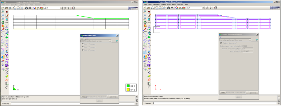
These conditions can then be assigned to the mesh or to the geometry which has been created in GiD. Some examples of condition assignments are shown below. The left hand side shows the assignment of point constraints (fixities) for the 3 DOF nodes in the mesh. As shown, multiple versions of the same condition can be assigned to separate groups of nodes. The nodes on the base are fixed only in the vertical direction (2nd DOF) and the nodes on the upper surface are fixed in the pore pressure DOF (3rd DOF). TO complete the 3 DOF node constraint assignments for this example, the additional nodes above the groundwater table should also have fixed pore pressure degrees of freedom (assignment not shown). The right hand side of the figure below shows the assignment of a condition which designates the node to which the Lysmer-Kulhemyer dashpot element is attached. As shown, the magnitudes of the bedrock shear wave velocity and mass density can be assigned during this step.
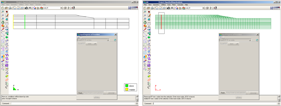
The process illustrated below can be used to assign the equalDOF conditions for the free-field columns discussed in the Dynamic Effective Stress Analysis of a Slope example. There are two conditions, Equal_DOF_01 and Equal_DOF_02. Each condition should be assigned to a separate free-field column. The left hand figure shows the assignment of the master and slave nodes on either side of the free-field column. It doesn't matter which side is designated as the master nodes or the slave nodes, however, the two sides must have opposing conditions. These steps can be completed in either the geometry or mesh views. The right hand figure shows the assignment of the interior nodes in the middle of the free-field column elements to the slave equalDOF condition. This step can only be completed after the mesh has been generated. These nodes don't exist in the geometry view, therefore,they cannot be selected in that view. For this example, a corresponding process to that shown below must also be performed on the right hand free-field column, only this time, the Equal_DOF_02 condition should be assigned.
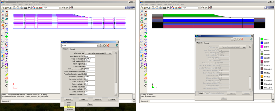
Material assignments are handled in a similar manner to the condition assignments. In the figure below, the left hand side shows an example material assignment form and the optional geometry objects to which materials can be assigned. As many materials as are desired can be assigned to the various surfaces (geometry view) or elements (mesh view) in the model. The default parameters for each material can be changed during the assignment process to suit the analysis. Parameters pertaining to the nDMaterials are on the 'Material' tab. Parameters associated with the nine node quad elements are on the 'Element' tab. The right side of the figure below shows the assigned materials for the slope analysis example. Separate materials are used for the free-field columns in order to ensure that the increased thickness of these elements are properly handled.
Once the mesh has been generated and all of the appropriate conditions and materials have been assigned, the OpenSees input file can be created by choosing 'Calculate' from the 'Calculate' drop-down menu. This is shown on the right side of the figure below. When GiD has successfully completed the generation of the input file, a dialog box like that shown in the left side of the figure below should appear. Due to the technique used to differentiate the corner nodes from the interior nodes of the nine node elements, the first time an input file is made from a new mesh, it is necessary to run the calculation process twice in order to obtain an input file which lists all of the nodes in the mesh. This is a quirk of the automatic node identification process in the UWnineQuad2Dup.gid problem type. The calculation process need only be applied a single time for the UWquad2D.gid problem type.
The steps necessary to use GiD as a post-processor for this type of problem are discussed in the Dynamic Effective Stress Analysis of a Slope example. A series of Matlab scripts are provided there which convert the data recorded by OpenSees during the analysis into a series of results which can be read by and visualized in GiD. Please refer to the other example for further information.
The UWquad2D.gid Problem Type
The UWquad2D.gid problem type was developed to be used with four node quadrilateral elements. This is the main difference between this problem type and the UWnineQuad2Dup.gid problem type discussed above. Restricting the scope to four node quad elements simplifies the template file, as there no longer is a need to differentiate between two sets of nodes based on nodal degrees of freedom. The material file is modified to exclude the element parameters which apply to the nine node elements, but do not apply to the four node elements. The conditions are similarly modified, with conditions which are unnecessary for the four node elements being removed.
The use of this problem type is very similar to using the UWnineQuad2Dup.gid problem type. One must create a geometry and mesh in GiD, assign the proper conditions and materials, and then generate the input file. There are somewhat fewer steps since the complications which apply to the nine node elements have been removed. With respect to post-processing, it is no longer necessary to create a post-process mesh file, the original mesh used to generate the input file can be used to define the mesh for the post-processor. The user must still create the post-process results file, however, for when working with four node elements, this file can be saved into the original project directory as opposed to a specially-created post-processing project directory.


